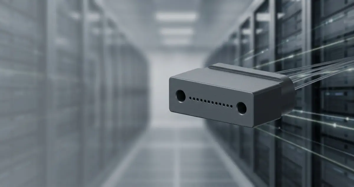
In data centers that support generative AI training, an enormous number of optical fibers are routed through the equipment. If each fiber had to be connected one at a time, AI infrastructure could not physically be assembled. Instead, the fibers are bundled and connected dozens at a time, with positioning errors tens of times smaller than the width of a human hair. A plastic part about the size of a coffee bean solves this challenge. That part is the MT ferrule, an ultra-precision component whose fiber hole positions are controlled to submicron accuracy (less than 1 µm).
In 2026, volume shipments of co-packaged optics (CPO) switches began. In some configurations, optical connection components now undergo the same board assembly process as electronic components. As a result, the requirements for MT ferrules—particularly the requirements for their materials—are beginning to change fundamentally.
This article first explains in plain terms what an MT ferrule is and how it is built. It then covers why demand is growing, the technologies behind its precision, the current state of ferrule materials and the turning point they face, the basics of specification selection, and the business opportunities for materials makers. The article moves step by step from the fundamentals to the latest developments.
1. What an MT Ferrule Is and How It Is Built
An MT ferrule is an ultra-precision component designed to connect multiple optical fibers at once. Ferrules made of polyphenylene sulfide (PPS) resin are widely used as the standard. This section first explains why the component is so important and then describes its internal structure systematically.
Dozens of Fibers at Once, With Submicron Precision
How does the MT ferrule solve the challenge described above—connecting many fibers at once with high precision?
The "MT" in MT ferrule is said to stand for "mechanically transferable," meaning that the ferrule can be connected and disconnected through mechanical positioning. The ferrule holds multiple optical fibers in a single part and is designed to connect all of them to a mating ferrule at once.
Why does this approach work? The difference is clear when the MT ferrule is compared with common SC and LC connectors.
| Item | Single- and dual-fiber connectors (SC/LC) | MT ferrule-based connectors (MPO, MT, etc.) |
|---|
| Fibers per connection | 1–2 | 4–32 or more |
| Connection density | Low | High |
| Installation efficiency | Fibers connected one at a time | Substantially shorter work time, since all fibers connect at once |
When fibers are connected one at a time, both work time and space grow as the fiber count rises. An MT ferrule positions fibers in groups of 4, 8, 12 or 24 at once, which makes it an excellent fit for high-density cabling.
Because of these characteristics, the MT ferrule has become a core connector component in optical communication systems. MT ferrules are used in the following settings:
- Data centers, which must fit large volumes of optical cabling into limited space
- Central offices and relay sites of telecom carriers, which support wide-area networks
- Next-generation infrastructure, where the number of fibers is rising rapidly as AI computing platforms expand
Layout of the Guide Pin Holes and Fiber Holes
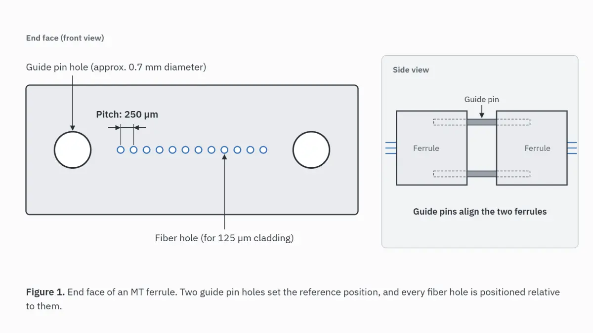
The end face of an MT ferrule has two guide pin holes, one on each side, with multiple fiber holes in a single row between them. This layout is the most important factor in the precision of multi-fiber connection.
The guide pin holes are approximately 0.7 mm in diameter. The fiber holes hold optical fibers with a cladding diameter of 125 µm. The two types of holes have clearly different roles.
| Hole type | Main role | Typical dimensions |
|---|
| Guide pin holes (2) | Positioning mating ferrules and preventing core misalignment | Approximately 0.7 mm in diameter |
| Fiber holes (one per fiber) | Holding and aligning the optical fibers | For 125 µm cladding (the hole is slightly larger to allow insertion) |
During connection, metal guide pins are inserted into the two holes and mechanically align the opposing ferrules. A single pin cannot prevent rotational misalignment. The design therefore uses two pins to constrain both position and angle. The guide pin holes also serve as the design reference: the position of every fiber hole is controlled relative to them.
Fiber holes are available in patterns of 4, 8, 12, 24 or more, depending on the fiber count, and the standard pitch is 250 µm. Even a slight shift in hole position leads directly to core misalignment and higher insertion loss. Manufacturing tolerances are strictly controlled at the submicron level to suppress multiple sources of error collectively, such as hole eccentricity and the clearance between the guide pins and their holes.
Enlarged schematic of an MT ferrule end face. Shows the dimensional relationship between the guide pin holes on the left and right (approximately 0.7 mm), the single row of fiber holes in the center (for 125 µm cladding) and the 250 µm hole pitch.
How the Ferrule, Housing and Adapter Share the Work
An MT connector system works only when three parts operate together: the ferrule, the housing and the adapter. Each part has its own role.
| Part | Main role | Function covered |
|---|
| Ferrule | Protecting the fiber end faces and positioning the fibers precisely | The basis of optical performance |
| Housing | Holding the ferrule and keeping it mechanically secure during insertion and removal | Ease of handling and durability |
| Adapter | Receiving two connectors and holding them in the mated position | Ease of connection and disconnection, and retention |
The ferrule aligns the fibers with submicron precision. The housing protects this delicate part from external force. The adapter receives the connectors on both sides and holds them in contact, while the guide pins handle the alignment of the fiber cores. Stable multi-fiber connection depends on all three parts working together.
MT connectors and MPO connectors are easy to confuse. Their relationship can be summarized as follows:
- MT connector: one type of multi-fiber connector that uses an MT ferrule (connector shape and dimensions are standardized in IEC 61754-5 from the International Electrotechnical Commission and in JIS C 5981, one of the Japanese Industrial Standards)
- MPO (Multi-fiber Push On) connector: a push-on multi-fiber connector built around an MT ferrule and combined with guide pins, a spring, a housing and other parts
- MT ferrule: the core component common to both connectors
In other words, whichever connector type is chosen, optical performance starts with the precision of the ferrule. Building on these basics, the next section examines why the environment around this component is now changing so significantly: the rapid expansion of AI data centers and the arrival of CPO.
2. Why Now: How AI Data Centers and CPO Are Changing Optical Connectivity
The MT ferrule has a history of several decades. Today, it faces an unprecedented turning point in both demand and technical requirements. Two developments are behind this shift: the rapid expansion of AI data centers and the emergence of a packaging approach called CPO.
This section explains why demand is growing and by how much, and how CPO changes the basic assumptions for optical connection components.
Explosive Growth in GPU-to-GPU Communication Is Accelerating the Shift to Higher Fiber Counts
In generative AI training and inference, thousands to tens of thousands of GPUs exchange data at the same time. Optical cabling supports this massive GPU-to-GPU communication, and multi-fiber optical connectors and MT ferrules are used at its connection points.
In AI-focused data centers, optical cabling density rises sharply compared with that in conventional data centers. The number of optical links between GPUs has increased greatly. High-fiber-count products such as 16- and 32-fiber connectors are being adopted more widely, in addition to 12- and 24-fiber types. Against this backdrop, major cloud providers each plan capital expenditure of more than $100 billion for 2026. These figures are companywide and include uses other than AI. Procurement of multi-fiber connectors is also rising sharply. At the same time, demand for higher-density cabling through narrower pitch and smaller fiber diameters is growing stronger, because operators must fit enormous amounts of cabling into limited rack space.
Market forecasts support this trend. In its report "Co-Packaged Optics (CPO) 2026-2036," IDTechEx forecast that the CPO market will grow at a compound annual growth rate (CAGR) of 37% from 2026 to 2036 and reach more than $20 billion in 2036. In Japan, Fuji Chimera Research Institute projected in its 2026 survey of optical communication-related markets that the CPO market in 2030 will be approximately 167 times its 2024 size.
What Are CPO and OBO? An Era When Components Pass Through Reflow Ovens
This section explains CPO, the central topic of this entire series.
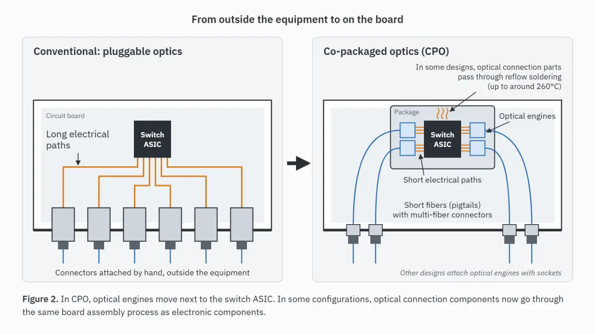
In conventional data centers, optical transceivers convert between optical and electrical signals. They have been mounted as pluggable modules, which are inserted into ports on the front of a switch. Optical connector components were parts that people connected by hand, outside the equipment.
CPO is a packaging approach that moves this optical-electrical conversion engine into the same package as the switch application-specific integrated circuit (ASIC), right next to it. CPO eliminates long electrical signal paths across the board. In this way, it achieves both higher capacity and lower power consumption. On-board optics (OBO), which mounts optical engines on the board, is also being developed in parallel.
As a result, in some configurations, optical connection components that used to sit outside the equipment now undergo the same board assembly process as electronic components—a process that includes reflow soldering. A typical example is a configuration in which a short length of optical fiber (a pigtail) and a connector remain attached to the optical engine while the engine is soldered to the board. However, some designs attach the optical engine with a socket so that it can be removed. Optical connection components do not pass through a reflow oven in every CPO design.
The specific assembly flow and peak temperature vary by manufacturer and product. Reflow with lead-free solder generally heats parts to a maximum of around 260°C. Components that once sat outside the equipment now sit on the board. A connector that people inserted by hand becomes a mounted component that passes through a reflow oven. Because of this change, not only the design approach for the component but also the requirements for its materials are changing significantly.
Section 4 explains in detail what problems this creates for conventional materials.
Conceptual comparison of a conventional pluggable structure (modules inserted by hand at the front of the switch) and a CPO structure (optical engines mounted on the board next to the ASIC and passed through the reflow process). Contrasts the move from "outside the equipment" to "on the board."
Developments in Japan: IOWN and Capacity Investment
In Japan, the Innovative Optical and Wireless Network (IOWN) initiative led by Japan's NTT is shaping long-term demand for optical connection technology. IOWN targets 100 times the power efficiency, 125 times the transmission capacity and latency reduced to 1/200. The core of IOWN is the All-Photonics Network (APN), which transmits optical signals without converting them to electrical signals. NTT said the launch of its APN service achieved the 1/200 latency target. NTT plans to provide commercial samples of a switch incorporating photonics-electronics convergence devices in the fourth quarter of 2026 and to commercialize the switch in fiscal 2026. The initiative is moving from the research stage to the implementation stage. As this trend advances, the number of optical connection points will increase, and requirements for component precision and reliability will rise.
Suppliers are already responding. For example, Japan's Hakusan, a Furukawa Electric Group company, plans to build a new plant in Kahoku, Ishikawa Prefecture, with a total investment of approximately ¥5 billion. Hakusan plans to start volume production of TMT ferrules there in April 2028. TMT ferrules are next-generation ferrules for very small form factor (VSFF) multi-fiber optical connectors. Surging demand and the transition to next-generation standards, both happening at the same time, define the current situation surrounding the MT ferrule.
3. Precision Decides Everything: Working at the 1 µm Scale
The value of an MT ferrule ultimately depends on the positional accuracy of its holes. This section explains why a precision of 1 µm is required and gives an overview of how process control, step by step, achieves that precision.
Why 1 µm?
One micrometer is one-thousandth of a millimeter. Its scale becomes clear when compared with the narrow path that light travels. In single-mode optical fiber, light travels through a region only approximately 9 to 10 µm across (the mode field diameter), approximately one-tenth the width of a human hair. An MT ferrule passes light between these narrow paths by placing them face to face. If the fibers shift sideways by just 1 µm, a non-negligible amount of light fails to couple into the opposite fiber and is lost. A shift of one-thousandth of a millimeter, too small to see, erodes the quality of communication itself. For this reason, low-loss single-mode products require fiber hole positions to be controlled at the submicron level. For example, one manufacturer said its reflowable ferrule for CPO keeps fiber hole eccentricity at 0.7 µm or less, even after heating.
The real difficulty of this precision lies less in the number itself than in the conditions. If there were only one hole, positioning that single hole to within 1 µm would not be impossible in ultra-precision machining. However, an MT ferrule positions optical fibers in groups of 12, 24 or 32. Every one of those holes must be aligned to submicron accuracy, without a single exception, for simultaneous multi-fiber connection to work. If even one fiber is misaligned, loss increases for that fiber, and the entire connector fails to meet its specification.
Hole position is not the only factor to control. The position of each fiber hole relative to the guide pin holes, pitch errors between holes, the straightness of the hole row and the tilt of each individual hole are all sources of error. These errors do not act independently. They accumulate and amplify one another. Submicron hole-position accuracy can be reached only by suppressing all of these errors simultaneously, in every hole. In volume production, this result must be reproduced in every molding shot. The reality of MT ferrule manufacturing is achieving alignment to within one-thousandth of a millimeter repeatedly, not just once.
Precision Comes From Control at Three Stages
Achieving this precision consistently in molding requires tight control at all three stages: mold design, molding conditions and post-processing.
| Control stage | Main requirements |
|---|
| Mold design | A mold structure that limits both hole position error and tilt angle |
| Molding conditions | Optimization of temperature, pressure and cooling time to minimize variation in shrinkage |
| Post-processing | Dimensional correction that accounts for dimensional change after demolding, plus environmental control |
When multiple holes are molded at the same time, variation in the 250 µm hole spacing must also be suppressed. Hole offset and hole tilt before polishing amplify positional deviation after polishing. For this reason, securing precision at the molding stage determines final quality. This accumulated process control makes submicron eccentricity possible across all fibers.
Note that this precision is not determined by the molding process alone. Submicron precision is guaranteed only through the entire process: ultra-precision mold machining, guide pin positioning technology, injection molding conditions and end-face polishing. In addition, volume production must maintain precision while accounting for mold wear, differences between material lots and seasonal changes in the molding environment. Ensuring this reproducibility in volume production is the real challenge on the factory floor.
Specific methods for molding conditions, dimensional measurement and quality control, as well as how each required property affects optical loss, will be covered in detail in the required-properties installment of this series (to be published).
Which material should deliver this precision? The answer is now beginning to shift. The next section examines this question.
4. Where Materials Stand: PPS as the Standard and New Material Requirements in the Reflow Era
The performance of an MT ferrule depends on its material as well as on molding technology. This section explains why PPS resin has remained the standard for so long and how the arrival of CPO and OBO is challenging that assumption.
Why PPS Became the Standard
PPS (polyphenylene sulfide) resin has been widely used as the material for MT ferrules. More precisely, ferrules are not made from general-purpose PPS as is. Each manufacturer uses its own proprietary compound reinforced with fillers such as glass fiber. PPS has held such a standard position that MT ferrules are commonly called "PPS ferrules." PPS became established because it offers the properties that optical communication components require:
- Low water absorption: The resin barely swells from absorbing water, which limits changes in hole position over time.
- Dimensional stability: The resin's low coefficient of linear thermal expansion keeps shifts in hole pitch caused by temperature changes extremely small.
- Heat resistance: The resin's high continuous-use temperature keeps its properties stable in the temperature environment inside equipment.
- Moldability: The resin is suited to volume production by injection molding and can reliably replicate hole shapes with submicron precision.
PPS was the material that could meet the requirement for submicron hole-position accuracy through molding. As long as the ferrule was a connector component used outside the equipment, it is fair to say that this choice was fully adequate.
The Turning Point: The New Hurdle of 260°C Reflow
With CPO and OBO, however, as described in Section 2, optical connection components in some configurations, such as pigtail designs, may undergo the same reflow soldering process as electronic components, with peak temperatures of up to around 260°C. Here, conventional PPS ferrules face problems. The question is not whether PPS can survive reflow temperatures. PPS itself is a heat-resistant resin that is used in surface-mount electronic components. The question is whether a ferrule, together with the fiber and adhesive bonded to it, can keep its fiber hole positions within submicron tolerances through the heating cycle:
- Heating in the reflow temperature range causes dimensional changes in the ferrule and may degrade hole-position accuracy that has been controlled at the submicron level.
- The ferrule resin, the optical fiber and the adhesive (typically epoxy) that fixes the fiber in its hole differ in coefficient of thermal expansion (CTE) and glass transition temperature (Tg). These mismatches cause a phenomenon known as "pistoning," in which the fiber end face protrudes from or retracts into the ferrule end face. Pistoning leads to higher insertion loss.
In other words, a conventional PPS ferrule that was ideal for a connector outside the equipment may not provide the submicron stability that a mounted component on the board requires.
Diagram of the pistoning mechanism during reflow heating. A cross section shows how differences in thermal expansion between the ferrule resin, the optical fiber and the fixing adhesive cause the fiber end face to protrude from or retract into the ferrule end face after heating.
Next-Generation Options: Evolve the Resin or Move Away From Resin
The industry is pursuing two main directions in parallel to address this problem.
- Next-generation resins: A shift to materials such as liquid crystal polymer (LCP) and specialty compounds, which offer low water absorption and high dimensional stability as well as a track record in reflow-soldered electronic components. LCP offers high heat resistance. However, LCP shows large anisotropic shrinkage due to molecular orientation. Using it requires careful development of the molding process, including mold and gate design.
- Ceramics (moving away from resin): Multi-fiber ceramic ferrules do not change shape even at high temperatures. They are positioned as an option for areas that resin cannot reach. However, mass-producing their complex geometry—many 125 µm micro-holes arranged at a 250 µm pitch—with high precision and at low cost remains difficult.
"PPS → next-generation resins vs. ceramics" is one framework for understanding ferrule materials in the CPO era. Readers should note, however, that this framework applies only to CPO and OBO applications that involve reflow. In conventional pluggable applications, PPS remains the standard. PPS is not being replaced. Instead, next-generation resins and ceramics are being added as options for reflow applications, and each material serves a different role. In practice, there are also options in between, including hard-to-machine materials other than ceramics and approaches that change the structure itself, such as fiber arrays using silicon V-grooves. A comparison of the properties of each material and structure, the role each one serves and the entry opportunities for materials makers will be covered in detail in the materials installment of this series (to be published).
5. Basics of Specification Selection: Fiber Count, Mode and Optical Performance
MT ferrule specifications involve several interrelated parameters, including fiber count, transmission mode and pitch. This section outlines the decision criteria to consider in equipment design and component selection.
Fiber Counts From 4 to 32
The fiber count of an MT ferrule is chosen from options such as 4, 8, 12, 16, 24 and 32, according to the number of optical fibers to be connected. In practice, 8-, 12- and 24-fiber types are the most common. However, 16-fiber interfaces have also entered the market to match 400G/800G-generation optical transceivers (QSFP-DD/OSFP).
| Fiber count | Fiber arrangement | Main applications |
|---|
| 4 | 1 row × 4 | Small LANs, testing and evaluation |
| 8 | 1 row × 8 | Four-lane parallel transmission inside data centers (SR4/DR4 types), building backbones |
| 12 | 1 row × 12 | 40G/100G data center connections |
| 16 | 1 row × 16 | 400G/800G-generation connections |
| 24 | 2 rows × 12 | High-density data center backbones |
| 32 | 2 rows × 16 | Next-generation ultra-high-density connections |
The 12-fiber type is the standard specification for MPO connectors and is widely used in applications such as 40GBASE-SR4, making it the de facto industry standard. The 24-fiber type arranges 12-fiber ribbons in two rows and is becoming more prominent in data center backbones that require higher-density cabling. The 32-fiber type stacks two rows of 16 fibers. Note that for 16- and 32-fiber types, the Telecommunications Industry Association (TIA) has established a standard, TIA-604-18, with a new guide pin pitch of 5.3 mm. Components for these types do not intermate with conventional 12-fiber components.
As the fiber count rises, uniform hole-position accuracy is required across all fibers, which makes manufacturing more difficult. The cost of ensuring uniform end-face polishing and the cost of inspection also rise proportionally. The most practical approach is to determine the number of fibers the system needs first and then consider mode and pitch.
Precision Differences Between Single-Mode and Multimode
Single-mode and multimode fibers require completely different levels of ferrule manufacturing precision. The biggest reason is the difference in core diameter. The smaller the core, the more directly a small positional shift leads to insertion loss.
| Item | Single-mode | Multimode |
|---|
| Core diameter | Approximately 9 µm | 50/62.5 µm |
| Hole-position accuracy requirement | Very strict | Relatively relaxed |
| Manufacturing cost | High | Low |
| Typical transmission distance | Several hundred meters to tens of kilometers | Up to several hundred meters (shorter at higher speeds; up to approximately 100 m in the 400G/800G generation) |
The selection criteria are simple. Single-mode is suitable for long distances or when future bandwidth expansion is expected. Multimode is advantageous for short distances, such as between racks, when the goal is to reduce deployment costs. When selecting single-mode, always check the ferrule's hole-position accuracy and its specified insertion loss.
High-Density Designs Through Narrower Pitch and Smaller Diameters
To meet the cabling density requirements of AI data centers, next-generation ferrules for fibers with smaller cladding diameters are under development.
| Item | Conventional MT | Small-diameter, narrow-pitch MT (example of products under development) |
|---|
| Cladding diameter | 125 µm | 80 µm |
| Fiber pitch | 250 µm | 125–127 µm |
| Fibers per row | Mainly 12 | 24 or 32 in a single row also supported |
The biggest advantage is that the fiber count can be increased substantially without changing the ferrule's outer dimensions. However, narrow-pitch products are not compatible with conventional MT ferrules. Using them alongside existing infrastructure therefore requires conversion adapters or a phased transition plan. Some products keep a fiber pitch of 250 µm even with 80 µm cladding, and they are intermateable with conventional MT ferrules for 125 µm cladding. Compatibility is determined not by cladding diameter but by fiber pitch and guide pin specifications.
Narrower pitch is not the only path to higher density. TMT ferrules, mentioned in Section 2, keep the conventional fiber diameter and pitch (125 µm and 250 µm) but make the ferrule and connector themselves smaller. VSFF multi-fiber optical connectors that take this approach are also moving toward volume production. For new projects, compare the required port density with the volume production schedule of each approach. Decide early whether to proceed with conventional types or wait for next-generation types.
Evaluation Criteria for Insertion Loss and Return Loss
Two metrics are needed to describe connection quality in numbers: insertion loss and return loss. Insertion loss is the optical power lost as light passes through a connection point, expressed in decibels (dB). Return loss indicates how strongly the light reflected back at the connection interface is attenuated. A larger value means less reflection, which is better.
| Item | Multimode | Single-mode |
|---|
| Guideline for maximum insertion loss (product examples) | 0.5 dB or less | 0.25 dB or less for low-loss grades |
| Return loss | 20 dB or more | 40 dB or more (with PC polishing; higher with APC polishing) |
Connector shapes and dimensions are standardized in the IEC 61754 series (IEC 61754-7-1 and IEC 61754-7-2 for MPO), and optical performance grades are defined in the IEC 61753 and IEC 61755 series. As a product example, some single-mode low-loss grade products (IEC 61755-3-31 Grade B, for 97% of random matings) guarantee insertion loss of 0.25 dB or less, with typical measured values slightly above 0.1 dB. Meanwhile, some reflowable products for CPO are specified at less than 0.35 dB, and some ultra-high-density narrow-pitch products at less than 0.7 dB (single-mode). Guaranteed values and measurement conditions differ by application, fiber count and density. Instead of writing only "IEC compliant" in a specification, calculate acceptable values from your system's link budget.
These numbers depend on how the end faces are designed to meet. A common method for reducing insertion loss is physical contact (PC) connection, which presses the end faces together to eliminate the air gap. PC connection therefore makes control of fiber protrusion during polishing important. For single-mode applications that require high return loss, angled physical contact (APC) polishing is used: the end face is angled at 8 degrees so that reflected light does not travel back. In MT-type connectors, PC or APC is selected according to the application and specifications. For example, reflowable ferrules for CPO and MMC connectors for VSFF use APC. The molding precision and material properties discussed in earlier sections combine with this end-face design to produce the values in the table.
During inspection, check the loss distribution across all fibers and pay attention to variation, not just the maximum value. Checking variation is a key point in quality control specific to multi-fiber connections. As the fiber count increases, the risk that a defect in a single fiber affects the entire connector also increases.
A CPO/OBO component adoption guide, covering reliability, standards compliance and where resin-based and ceramic-based options diverge, will be published as a follow-up in this series.
6. Business Opportunities for Materials Makers
So far, this article has examined the market from the perspective of companies that make and select components. Finally, it examines the same market from the perspective of companies that supply materials.
The Qualification Barrier Becomes a Barrier to Entry
Resins for optical communication components form a market that cannot be entered simply by extending general-purpose grades. The market requires properties engineered on the assumption of submicron dimensional control. Once a material is adopted, the component maker optimizes its molds, molding conditions and inspection criteria for that material. For this reason, the material is not easily replaced. The strictness of the requirements itself becomes a barrier to entry, and once a material is qualified, it tends to stay in use. These mechanisms define the structure of this market.
Now, the shift to CPO is beginning to open a gap in this structure. If the assumptions behind PPS, the conventional standard, weaken, materials will be selected again. In other words, a window is opening for new entrants. The race to develop next-generation resins is one of the few opportunities for materials makers to clear the qualification barrier as new suppliers.
An Overview of the Properties Required of Materials
The following list covers the full range of properties required of ferrule materials in the CPO/OBO era. For CPO applications, the top priorities are heat resistance to withstand 260°C reflow and dimensional stability, so that hole positions remain unchanged after heating. Low water absorption and low anisotropy during molding come next. This order is a rough weighting.
- Heat resistance (reflow resistance): Dimensions and optical performance change little even after a reflow process at around 260°C. Heat resistance is a prerequisite for CPO applications.
- Dimensional stability: The material shows low linear thermal expansion and low warpage. Dimensional stability is the foundation for maintaining hole pitch accuracy.
- Low water absorption: Hole positions do not move under changing temperature and humidity.
- Low anisotropy: When fillers are loaded heavily to achieve submicron precision, shrinkage and thermal expansion differ between the flow direction and the transverse direction (anisotropy). This anisotropy causes warpage and hole misalignment. Successful molding depends on suppressing this orientation-induced distortion.
- Replication accuracy: The material can mold and replicate submicron hole shapes consistently.
- Mating durability: The material does not wear or deform even after repeated insertion and removal.
- Flame retardance: UL94 V-0 is often required. This requirement is important for data center equipment.
- Flowability: The material can fill to the far ends of fine, thin-walled sections. Flowability becomes more important as fiber diameters and parts become smaller.
The required-properties installment will explain how each of these properties affects insertion loss. The materials installment will cover development trends in next-generation materials and the role each material serves.
Summary
The MT ferrule is an ultra-precision component that positions multiple optical fibers with submicron precision and supports high-capacity optical communication.
Key points of this article:
- The expansion of AI data centers is accelerating the shift to higher fiber counts and higher density. With the arrival of CPO, some optical connection components are changing their role, becoming mounted components that pass through reflow ovens.
- Conventional PPS ferrules face a new challenge in reflow processing: keeping fiber hole positions stable to submicron accuracy through heating. In that area, materials are being selected again along the lines of "next-generation resins vs. ceramics."
- Selection of fiber count, mode and optical performance rests on this foundation of precision and materials.
Materials makers, molders and equipment designers each need to watch different points. What they share is that precision and materials are the starting point for everything.
This series will continue with in-depth coverage of material challenges (materials installment), the relationship between required properties and optical loss (required-properties installment), a CPO/OBO component adoption guide, an overall map of optical connection components for data centers and interviews with key industry players.
PlaBase's resin and molding material property database lets you check the properties of each material grade.
For questions about selecting or sourcing materials for optical communication components, please contact us here.